

More bits arrived. I made an annoying mistake with the motor sockets so need to wait for more cables…
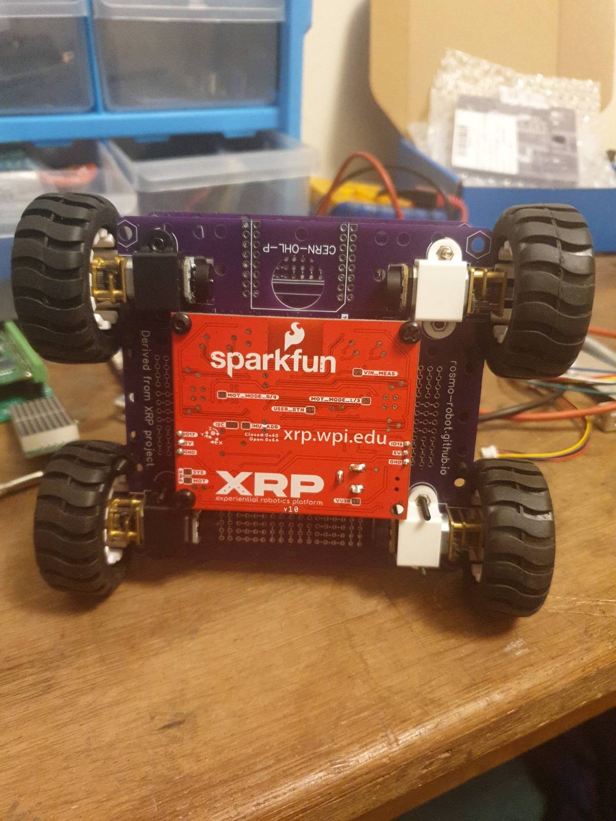
I did a new version of this PCB I’m calling XRP-X4

What’s the correct way to attribute it? I see the the board is CC
-by.
As of now I have
- Added text ‘derived from XRP project’
- Retained urls to xrp.wpi.edu
- Removed the Sparkfun logo
I’ve removed the logo not to obscure the origins of the board, but so Sparkfun don’t get complaints about my stupid errors.
Is that OK? Happy to make any changes to the silkscreen to meet the requirements of the CC-BY or the project preferences.
During checking JLPCB also flagged this as a possible issue

Is it desirable to remove that in future iterations?
That looks sweet!
Regarding attribution, the original design (and most SparkFun products) are released under CC BY-SA 4.0. Check the official license info, but the short version is that you need to attribute the original designer (me!), and share your source under the same license. I’m not actually sure what the rules are around logos, but probably best to remove the SparkFun logo to be safe.
Looking at the EasyEDA link you shared, looks like some things didn’t get converted/copied correctly. There are some extra solder jumpers (like the issue JLC flagged), some extra test points, the copper under the Pico W antenna needs to be removed, and the copper pour boundary isn’t a clean rectangle, so it’s missing some vias. I’ve circled some things that immediately stand out to me:

Original design for reference:

Hope this helps!
1 Like
Ah great stuff, it’s a lovely little board, nice one.
When I started I didn’t anticipate actually fabbing the PCB with the controller components, just using it as a mounting plate. I expect that Sparkfun will always be able to produce the controller at a lower cost than I could.
I would really like to use the board with an esp32-s3 pico through, so I may end up making some, unless Sparkfun could supply them without the Pi? Or even better with female headers for the Pi. Would there be many changes needed to enable TH Pi headers?
I don’t anticipate us selling a different version of the XRP Control Board any time soon, and certainly not without a microcontroller. If you’re feeling adventurous, and you have the skills and tools available, one option would be to de-solder the Pico W from the Control Board and solder something else onto the pads. I personally think that’d be easier than trying to manufacture your own version from scratch. Just know that you’ll have limited tech support since this is going far beyond the intended use case of the XRP, but we’d love to see what you come up with!
1 Like
Thanks, I’ll consider that.
The issue for me is the Pico is it doesn’t support Wifi transport under MicroROS. I’ll try and just get the software fixed…
I also found out that Bringsmart would produce cables to connect the XRP to their N20 encoder motors. 42cents US each including postage. The problem is they will only do 100pc. I don’t suppose Sparkfun might get a batch and add them to your store?
If there’s enough demand from customers, then we would consider reselling that cable. I’ve not heard of anyone else asking for it, but I’ll start the counter!
1 Like


New iteration of this. Still don’t have a good solution for cables to connect the motors. I can get four sets of 1mm > 1.5 mm pre-crimped cables for $25 but I only want one set.
1 Like
As I couldn’t find affordable cables for end users to connect with the XRP board this project has morphed into Ziobot

I’ve retained the Pi A/ XRP mount holes on the PCB so it could still be used with the XRP board
2 Likes