Hi! I’m an FTC Student from 18603 Terabridges. We are hosting a summer camp with the XRPs starting Monday next week.
I was testing Pestolink on the XRP using the front loader robot configuration that Experiential Robotics has an article about. This was for the Orbit Odyssey games.
The scoop requires using a larger more powerful servo so we used a standard 5V amazon servo. I plugged it into the same servo port (Servo 1) as advised by the article. I ran Pestolink on the XRP and tried moving the servo and it work for a few seconds, but then the servo froze for a moment and Pestolink said on its telemetry “Timeout?”. I don’t know if this was a power issue or something, but at this same moment the SYS light turned off.
My computer’s xrpcode client disconnected from the robot. I tried reconnecting in every way, using the cable and then the wifi. I power cycled it, swapped out the batteries, unplugged everything, none of that worked. I tried to erase its flash memory by entering the Raspberry PI board’s storage on my computer. A lot of sites told me you could do that by holding the BOOT button, clicking RESET, and letting go of BOOT all while plugged into your computer. This didn’t do anything and I wasn’t able to access the board’s files.
I also tried all of this with another computer. We believe the cause of this to be the servo but the XRP website did have an article endorsing the front loader design so I am not sure.
Here is a picture of the board while it is on:
Is it possible to bring those board back to normal or is it fried? Does anyone know what the cause was? Thank you!
This does sound frustrating. There are a number of 5v servos out there, and the other number that matters is how much amperage the servo can pull. Can you send the link of the servo you are using? Since you are using the latest XRP controller, it does have a fuse to protect against pulling too much power, this should reset, but If you or someone on your team feels electrically savvy, you can take the board out, and disconnect all external devices, including the servo. Then on the back of the board there is a solder jumper pad labeled BYP. It is not closed. You can temporarily close it and plug in the batteries and turn it on to see if both red LEDs come on.
For more information look at the Solder Jumpers section of the XRP hardware over view XRP Controller Overview - SparkFun XRP Controller Hardware Overview
@SparkFro any other suggestions?
Thank you for replying!
Those are the servos we used.
I will try temporarily closing the BYP jumper tomorrow and get back to you about the results.
@Fgrossman
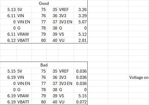
Just tried closing the bypass jumper pads this afternoon and it did not solve the issue. The SYS light continued to be off. We also measured the voltage on both pads of the bypass and they were the same so the fuse must be working.
Here are some voltage data tables comparing our bad board and a good board. Hopefully this can provide more insight on our issue.
Thank you for your help!
I would look to see if you see any bent pins in any of the connectors. We have seen this with shorted out pins before. If not we will have to see if @SparkFro has any other suggestions. The servos you are using according to the Amazon page can draw up to 3A at 5V if stalled. That is more than some of the components on the board can handle. The ones in the design were around 1.5A at 5V stalled. This page has the schematic and some of the limits of the components. https://cdn.sparkfun.com/assets/c/5/3/5/2/XRP_Controller-Schematic.pdf
Howdy!
Here’s the high-level power diagram from the board schematic for reference:
- MOT LED is on:
- This LED is powered by the 5V rail, which is regulated from the battery voltage. This is primarily used to indicate the actuators have power, but it also implies that the battery voltage rail and 5V rails are both fine. It also implies the fuse on the battery input has not tripped, so closing the BYP jumper will not have any effect.
- Side note - I would advise that you do not close the BYP jumper to debug power problems. If you have power problems, that’s when you most need the fuse to be functional, not bypassed, otherwise you could blow something up or possibly start a battery fire in extreme cases. The BYP jumper is only there for users who know for certain that they need to bypass the fuse (eg. you need high sustained current, not just peak current), and have done the engineering the verify that nothing bad will happen (eg. not exceeding the current limitations of the traces in the PCB and connector pins, and your battery can actually supply enough current).
- SYS LED is off:
- This LED is powered by the 3.3V rail, which is regulated from the 5V rail. The microcontroller, sensors, and other system components are powered by this rail, so if the LED is off, you won’t be able to actually do anything (eg. program or access bootloader), since the microcontroller isn’t powered.
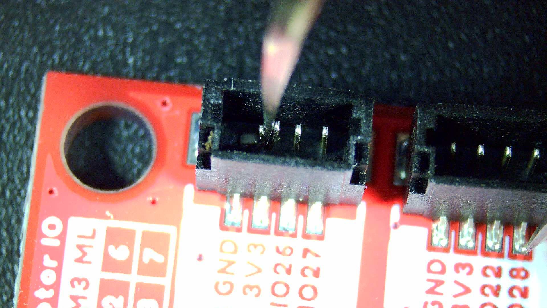
- This LED being off typically indicates a short on the 3.3V rail. You can try using your multimeter in continuity mode to confirm this (probe between the 3.3V rail and GND with power off). Most commonly, that occurs with bent pins in the small black JST connectors at the top of the board. Inspect them closely to see if any pins are bent. This is what that can look like, for reference:
- If that is the case, you can bend the pin back with a pair of tweezers. You have to get it between the pins, a magnifying glass or microscope helps a lot if you have one! Be careful to not bend the pins back and forth too much, otherwise you can fatigue the metal and break off the pin.
- I understand you said the SYS LED turned off right after moving the servo. The only reason I can think for this happening is if the servo somehow applied 5V to the PWM IO pin and fried the microcontroller, though I don’t really see a mechanism for how a servo could do that unless it was plugged in wrong? Only other debugging step I can think of right now is to unplug everything except power, and see if that changes the behavior.
Hope this helps!